Date Assigned: Wednesday, February 26, 2009 Date Due: Wednesday, March 4, 2009
(items 2 and 3 are due in class at 9:00 AM)
Reading:
For March 2 and 4,
please review Chapter 6 and begin reading Chapter 7, Sections 7.1, 7.2, and 7.3.
Please solve a variation of Problem 1 on Exam 1
(the solution to Exam 1 is posted on Blackboard).
The circuit for this problem is an ideal voltage source
v1(t) in series with a capacitor (C farads) in series
with an eleven ohm resistor.
The voltage v2(t) is measured across the resistor
so that v1(t) = vC(t) + v2(t)
where vC(t) is the voltage across the capacitor.
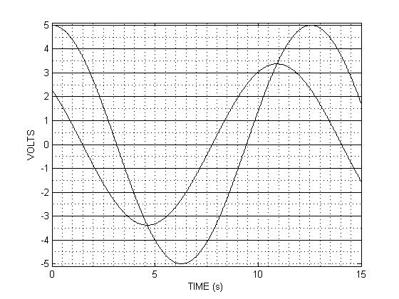
The voltage waveforms for v1(t) and
v2(t) in sinusoidal steady-state
are shown below.
Please estimate the value of the capacitance, C (in farads).
Please solve a variation of Problem 3 on Exam 1.
The sinusoidal source voltage is 120 V (rms) with frequency 60 Hz.
Load 1 is a 40 ohm resistor in series with a 53.1 mH inductor.
For Load 1, compute the following quantities:
Complex power,
average power,
apparent power,
peak amplitude of the source current (is(t)),
power factor (include lagging/leading),
peak value of instantaneous power.
Let us define Load 2 as Load 1 in parallel with a capacitor with value C.
Find the value for C (in farads) so that the power factor equals 1
for Load 2.
For Load 2, compute the following quantities:
Average power,
apparent power,
peak amplitude of the source current (is(t)),
peak value of instantaneous power.
For Load 2,
draw a phasor diagram showing the phasors for the source voltage,
source current Is, and the currents I1 and I2.
If you did not submit the summary pages for your lowpass and
highpass filters in Lab 4, then
please submit them by Friday, March 6 at 10 AM.